ADAS System Topics
2018 Subaru Forester
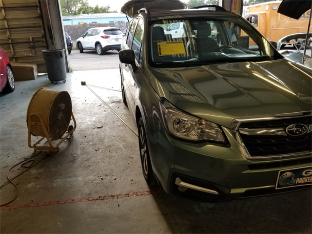
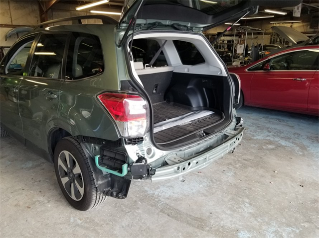
This vehicle was hit in the rear and was repaired. During the repair, the blind spot radar units were removed and replaced. Due to their replacement, a calibration is required.
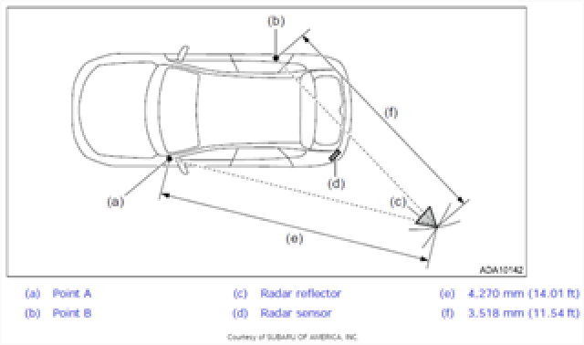
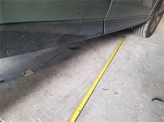
The calibration is done by making measurements from reference points on the ground that are made by suspending a plumb bob from reference points on the body.
The OEM calibration method is done by making measurements from reference points on the ground that are made by suspending a plumb bob from reference points on the body. You then measure from these points to set distances given by the OEM service information to place the proper recalibration target.
The Snap-on EZ ADAS and or Tru Point uses the latest technology such as lasers and/or camera positioning to accurately and quickly place the targets to OEM specifications.
By determining the intersection on the tape measures at the specified distance from the marked reference points, our calibration target placement can be established.
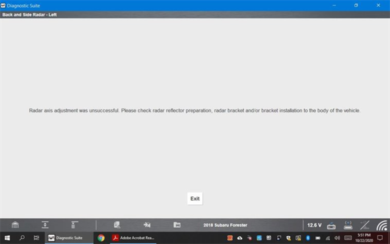
Once our target is in place, we can begin the calibration. To do the calibration, the scan tool is connected to the car and the proper ADAS functional test is accessed to invoke the calibration.
It immediately fails on the driver's side leaving us to try and determine what the issue is. Our first check is to go back and verify all of the reference points and measurements. We also want to make sure there are no nearby objects causing interference.
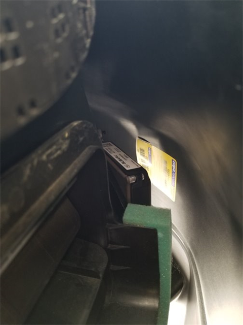
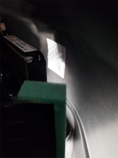
After rechecking our setup, we decide to peel back the bumper covers and take a peek at the blind spot radar units to see if they are out of alignment. We notice that there is a sticker on the inside of the bumper cover, right in front of the radar sensor!
Knowing that the radio waves emitted from these units can read through less dense materials like bumper covers, it seemed a little odd that a sticker could cause such an immediate and consistent failure - until we reached in and attempted to peel the sticker off only to find a metallic VOID tamper sticker!
We could not find any statement from Subaru stating that aftermarket bumpers must not be used. We were able to perform the calibration on the passenger side with no issues.
The shop removed the remaining sticker residue, and the calibration was completed successfully.
by Jason Gabrenas and Mike Reynolds
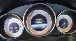
This vehicle had been in a collision and repaired, however they were unable to deliver it as a warning message indicating ‘lane keeping assist inoperative’ was displayed in the instrument cluster.
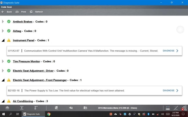
A code scan with the ZEUS® revealed a code for loss of communication with the multifunction camera.
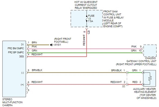
The first step in our diagnostic approach for this code will be to look at the wiring diagram and use it to determine the most likely potential causes of our loss of communication. In this case the circuitry is very simple: one power, one ground, and two CAN communication circuits.
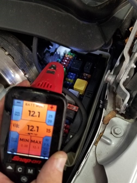
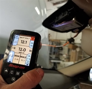
The multifunction camera is located on the windshield of this vehicle. Because this vehicle was in a collision, our thought is that the most likely causes would either be a camera left unplugged after a windshield replacement, a blown fuse that could have been shared with other components, or wiring that could have been damaged in the accident. After checking to make sure the camera was plugged in, we accessed the front SAM (Signal Acquisition Module) and verified that there was power on both sides of fuse 13.
Check out Guided Component Tests on compatible Snap-on platforms for vehicle specific waveforms and pin assignments.
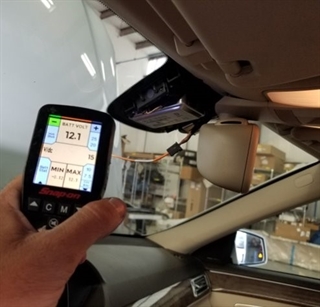
Just because our fuse was blown, doesn’t mean that the power is getting to the camera. Moving our testing to the camera itself, we verified power and ground at the camera. Since this circuit is protected by a 7.5-amp fuse, it was unlikely that the camera could pull more than an amp or two which tells us that voltage drop is highly unlikely as a cause of this fault.
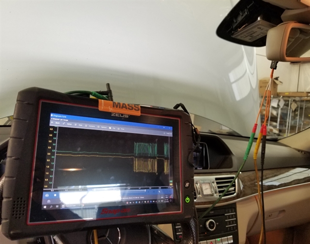
With power and ground to the module, the only thing left to check was the CAN signal at the camera.
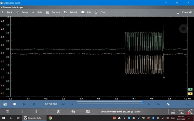
We use the camera’s ground and connect one scope lead to each CAN circuit and dial in the waveform.
Looking at the CAN waveform, we see a clean looking signal. The CAN high and low mirror each other consistently. With that information, we verified all signals to the camera are good, so we recommended replacing the camera.
